The Finnish X band amateur radio allocation is from 10000–10500 MHz. Narrow band SSB/CW constesting occurs between 10368 and 10370 MHz.
Best news: The antenna systems tend to be small.
Good news: N and SMA connectors and handyform 3.5 mm coax can still be used!
Bad news: connector and cable losses become noticable on this band…
The heart of the system is a Kuhne Electronics 3 cm transverter I built some years ago. An ADF4351 based ZLPLL is used as the local oscillator, disciplined by a cheap OCXO or external 10 MHz GPS Trimble Thunderbolt reference.
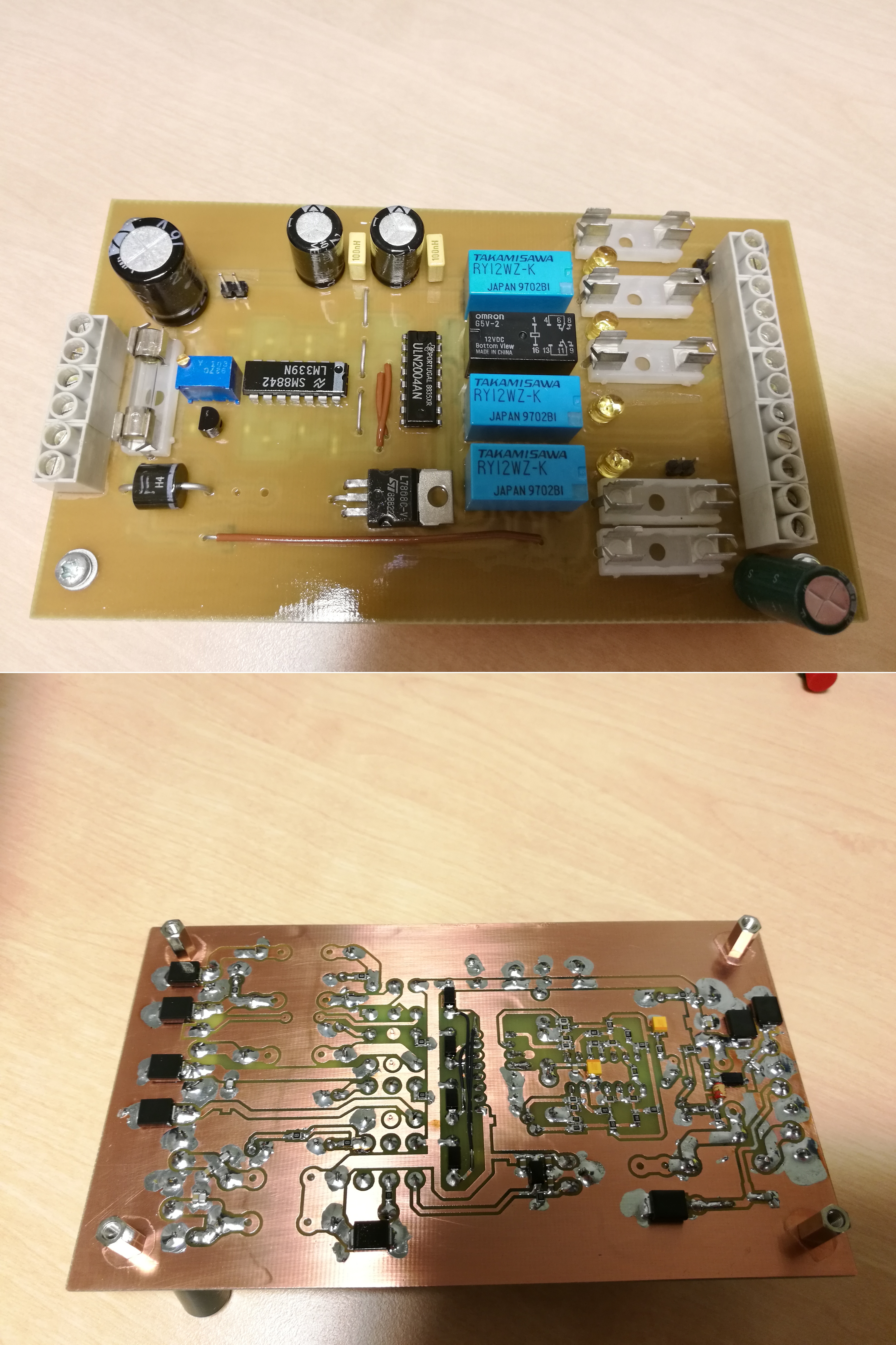
A lot of additional circuitry was needed to do the magic, such as the sequencer board which also functions as a power distributor, containing the necessary fuses, filter capacitors and TVS diodes for transient protection. The core of this board is a RC circuit and and LM339 comparator with hysteresis. Its quite slow to switch between RX and TX, taking 100–200 ms for each step and having four steps in total. But I don't see how that could a problem for tropo ssb/cw. The 7808 regulator is for supplying the voltage for FT-897 TX INHIBIT function, a very cool feature which blocks the RF output on TX as long as positive voltage is applied to the ACC connector. That feature is actually one reason why I chose FT-897 as an IF rig! However, YOU should be careful when experimenting with that feature, since it is poorly documented, and I will not be responsible for anything you break ☺
There is also a latching relay driver to operate an ancient French Radiall relay, which toggles between the internal 10 MHz OCXO and the front panel BNC connector. The circuit is based on this StackExchange page but I added a PNP Darlington to drive the relay and changed the components values to obtain a ~200 ms pulse. No datasheet could be found for the relay so the pulse length was determined using the Stetson-Harrison method. The circuit can be found here. Flyback diodes and capacitors are not shown, but are quite necessary to make this work.
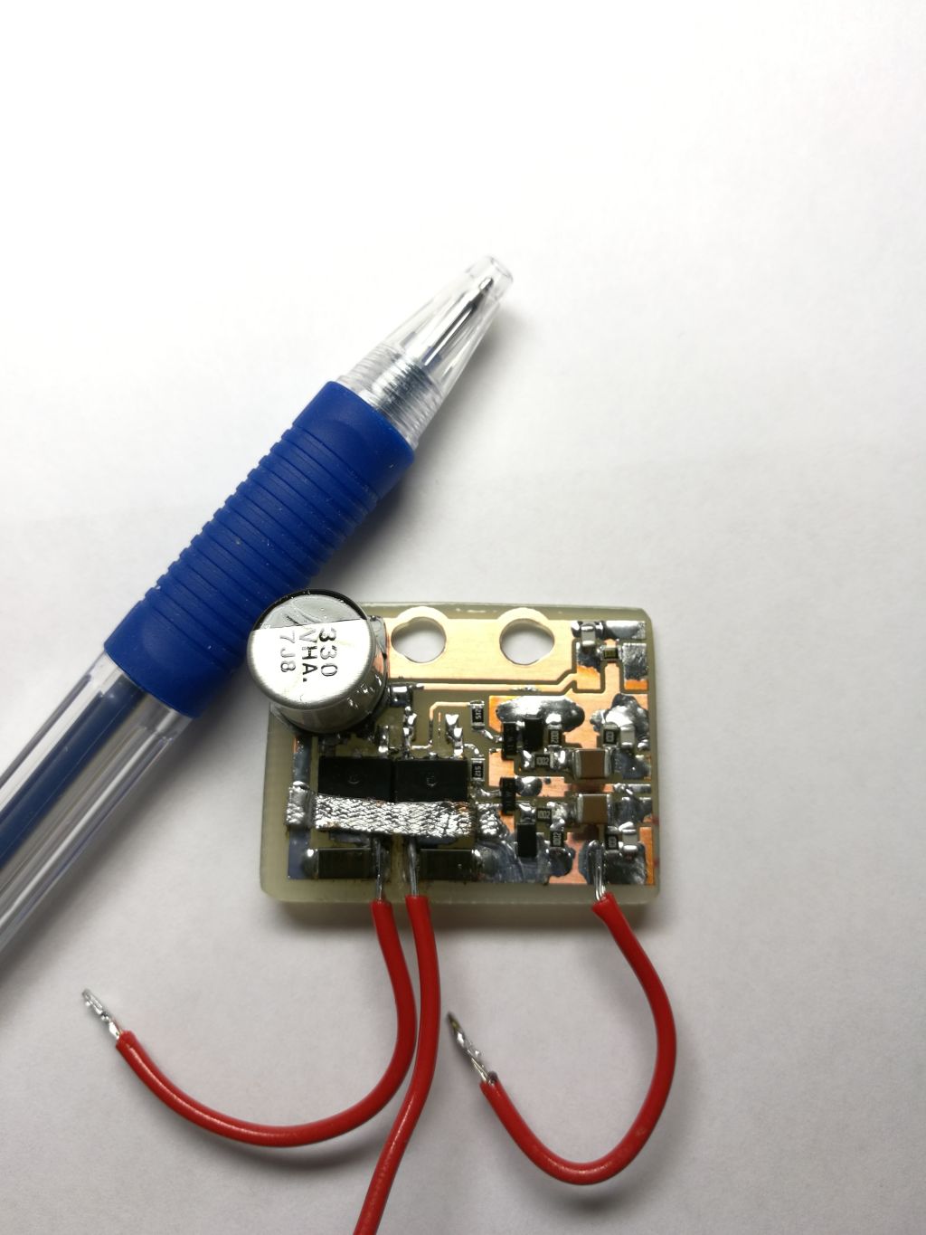
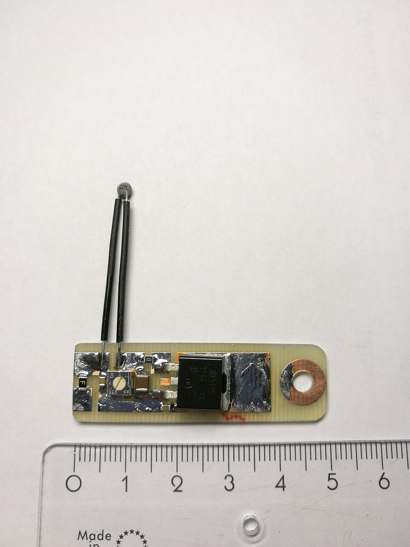
In the original system the fan was set to run only on transmit. A quick thermal test was done by letting the transverter run on receive for 6 hours while measuring the temperature from the inside. The temperature rose from 22 to 36 ℃, and remained constant. Several knowers from IRC (thanks!) said that I should aim for improved thermal stability. Perhaps to improve the frequency accuracy …? In any case now when I think of it, it sounds like a the polar opposite of a good idea to run the fan if its -20 ℃ outside! So I construced a thermostat fan controller using the circuit (added a fuse though) presented on OZ1PIF's webpage and installed it in the middle of the enclosure. It works quite well except the fan makes a high frequency whining sound if the voltage (temperature) is too low for the fan to start but above ambient...!
The receive noise figure was 1.5 dB and conversion gain was 44.3 dB, so less than on decibel is lost in the N–sma adapters, 3.5 mm handhyform cabling and SMA relay. Output power measured from the N connector was 1.6 W, implying 2 dB losses from the isolator, cabling and SMA relay. Can you spot where the 10 GHz signal runs through a piece of Suhner Enviroflex rated only up to 8 GHz?
Updated 6.3.2018
Disclaimer: This webpage is for general information purposes only. It is not professional advice and contains opinions and most probably inaccuracies. Viewer discretion is advised.