With AMSAT P4A almost here (scheduled for launch in 2018) its time to build equipment for it. AMSAT-DL Journal 2/2015 tells us the key information:
| Frequency | Polarization | Bandwidth | |
|---|---|---|---|
| Uplink | 2400.175 MHz | RHCP | 250 kHz |
| Downlink | 10489.675 MHz | Linear vertical | 250 kHz |
It was said somewhere that a successful QSO from Finland takes a 90 cm diameter dish and 5-10 watts of TX power. Some quite convincing satellite guys swore in the name of transmit power control, but on the other hand our guide in becoming a true and credible radio amateur says that anything less than 1 kW is for preamp only AND that a true ham always uses full power. The truth is out there... Anyways that sets the goals necessary for P4A communication:
This design is from AMSAT-DL August 2016 issue. Instead of aluminium, the oxidation of which results in contact issues, the parts were made from 1.5 mm sheet copper. Laser cut plywood jigs for soldering and drilling were a great success, and with copious amounts of liquid flux the feed was soldered. 50 W & 80 W Weller soldering irons and an Aoyue hot air soldering iron were necessary, wish I had had MAXIMUM SIZE iron tips (and 250 W irons...).
RF characteristics were measured at our local club OH3TR. At first attempt the return loss at 10.45 GHz was 14 dB and -20 dB at 2.4 GHz. The first was measured using directional coupler and power meter and the latter using HP VNA. By carefully filing the SMA probe the 3 cm return loss was tuned to at least 17 dB, which is the measurement limit imposed by the coupler. While this was rather straightforward, considerable effort had to be done to optimize the return loss and axial ratio at 2.4 GHz. In the first revision only one could be acquired, with the feed tuned for adequate axial ratio (in this case less than 3 db) the return loss was less than 10 dB, and with the tuning screw optimized for good return loss (20 dB) the feed was essentially linear.
When the screw was adjusted for good (<1...3 dB) axial ratio the impedance presented by the feed was quite inductive, so in the second revision a 7 mm piece of 5 mm OD copper tubing was soldered on the N-connector center connector. This tube was in turn hot-air soldered to the 2.4 GHz radiator disc. In concept this worked, but in reality the feed was now leaning to the capacitive side of the Smith chart. If I could rewind time I would have opted for a piece of outer shield cut from 3.5 mm OD semi rigid coaxial cable instead of the 5 mm OD tubing. Nevertheless, with this modification significantly improved results (return loss >10 dB and axial ratio <1 dB) were already acquired. Before final measurements the oxidation caused by hot air soldering was removed using steel wool saturated with soap, known as Pata Pata.
The feed alone was not optimized further, since in the end-use application the close proximity of the parabolic reflector will surely affect its performance. Final and proper testing should be done outdoors with the feed in place. The accuracy of results are also surely impaired by our rather non-ideal measurement setup erected hastily in one office corridor. The setup consisted of 2.4 GHz ISM band linearly polarized antennas, bandpass filter tuned at 2.4 GHz and copious amounts of cardboard and duct tape. There must have been reflections, so the results and analysis should be taken with caution.
N.B. It seems like the outer diameter of the 5mm copper tubing was "quite close" to the screw/nut arrangement depicted in the original article. One could suppose that the dimensions of the connector-to-radiator portion of the feed are critical for good performance...
Ari, OH3LWP, kindly brought a 100 cm dish to our local club for the P4A link project. The dish has a peculiar f/d of 0.5. As the "AMSAT-DL" p4a feed is designed for f/d 0.4 - the "mismatch" may cause increased sidelobes, which most probably increases the received noise. I hope that doesn't cause problems.
Finally, a feedhorn support boss frame was laser cut from plywood and the feedhorn was mounted in front of the dish. This is for temporary use only, yet I'm quite convinced it will get me "on air" when the time comes. The materials will not like rain, but neither do I, so who am I to complain. A more weather resistant choice would be laser cut acrylic, but then all the other parts should be weatherproofed too.
The required 5-10 W of RF power at feed can be acquired from surplus TELIA 2.2 GHz amplifiers. I would prefer a bit more, lets say around 10-20 W at PA in a maximum of 1dB gain compression. The 3 dB power margin would allow longer and lossier coaxial runs to the roof. The new (as of 2017) Kuhne Electronics P4A UP-converter has 20 W output power, so that could be one target.
Recently I bought a TELIA 2.2 GHz power amplifier module, which is a three-stage amplifier with high gain (48 dB) and P1dB of 15 W. P1dB stands for output power at 1 dB compression, more on that on this excellent Microwaves101 page. Moreover the amplifier is rather broadband, performing well in a frequency range of 2.2-2.4 GHz and possibly even beyond. All in all it looks very suitable for P4A. The finals are two Motorola MGF0911A GaAs fets driven parallel through Anaren 1A1306-3 3dB hybrids. The hybrid couplers are very broadband, with datasheet reporting adequate performance from 1.8 to 2.7 GHz. This might explain the good performance at 2.32 and 2.4 GHz, quite far from the original design frequency. I heard that two similar 3 dB couplers might make two non-optimally matched transistors work in parallel, which might well be the case if the transistors are point-matched at original intended operation frequency.
However, the unmodified amplifier had some downsides, the 15 W P1dB is tad low compared to the P1dB of 41dB of the MGF0911A finals, and at 1 dB compression the second harmonic was only around 50 dB down. Performance data of unmodified amplifier measured at 2.32 GHz is seen here, and performance was similar at 2.4 GHz. In real world the gain was even higher as the input cable losses were not taken into account. Input cable was approx 1 metre of RG178. So a low- or bandpass filter was necessary to fulfill the FICORA requirements for spurious emission. Luckily I had a good bandpass filter available, but that reduced the P1dB output power further, down to 13.2 W. I thought the problem originated from the first three MMIC gain stages being driven too hard. Quite possibly for stability reasons the stages had attenuators in-between. I decided to remove the first three MMIC gain stages including the attenuators, leaving only the last two power GaAs-FET stages and something which appeared to be a RF-switch assembly to hold off RF before GaAS fets were properly biased. The modification was a success, improving the P1dB to around 21 W. The amplifier performance chart at 2320 MHz can be seen here. In this measurement all cable losses were taken into account and the attenuator characteristic were measured before and the actual values at 2.32 GHz were used. The modification I believe also reduced amplifier noise figure greatly due to the removal of the input attenuators. Moreover I realized that the isolator assembly acts as a low-pass filter, and I could omit the band pass filtering, since with the insolator the harmonics were well below -60dBc and the level was below the FICORA requirement.
Here are some pictures of the finished amplifier: Picture1 Picture2. One M3 tap was lost during manufacturing of the heatsink, and for high duty cycle modes a fan would probably be required. An isolator acts as a low pass filter and is also useful in eliminating load-pull effects caused by the not-50 Ω impedance presented by the feed. Also the efficiency is rather low due to the use of a 13.5 V supply instead of the intended 12 V. The amplifier has linear LDO regulation to some GaAs FET voltage (presumably 10 V or less), and better efficiency is surely acquired if driven at 12 V.
I intend to operate on the narrowband segment using SSB, so my FT-897 (now repaired!) or FT-817 with IF tap (sold – I didn't like the small VFO knob...) output shall work as the exciter (transmitter) on 70 cm. Using 70 centimeters as the IF will allow me to use broader lower-Q filters which are easier to fabricate. I planned to build the converter from a variety of connectorized modules: a local oscillator, a mixer, filters and buffers are needed (at least). I will use an ADF4351-based ZLPLL by Wayne, ZL2BKC, to drive a Mini-Circuits level 7 mixer ZEM-4300+ via a MMIC buffer chain. I have plenty of Mini-Circuits MAR and Agilent MSA-0686 MMIC amplifiers to be salvaged from some surplus bonk I bought from local ham fest.
Now I am actually thinking of using a simple diode mixer and microstrip filters on FR4 board (who cares about losses in post-mixer filtering) which may be well design-able using QUCS and SONNET.
Can be made from certain PLL LNBs which can also be modified further by e.g. replacing the input horn with sma connector and replacing the original crystal with a high accuracy external reference. F3YX even screwed a WR75-SMA waveguide transition on the feedhorn mouth and claims it works with less than 1 dB losses! Lots of information and good pictures on this interesting LNB is available on HB9AFO's webpage, but apparently one has to be careful to purchase the "right" model, since as illustrated on DD0YRs webpage only small differences in markings may differentiate between suitable and not models... Alternative approach is Kuhne electronic AO-40 downconverter PCB built using parts from Eisch-Kafka-Electronic. Kuhne also is also advertising their new 10 GHz P4A converter that looks a lot like LNB (not yet available as of 4/2018). (Available as of 8/2018!) So many options to choose from!
I got one Octagon OSLO PLL LNB that G4JNT (and others) claim to be suitable for narrowband SSB/CW reception, ZS6BTE however mentioning that the device needs to stabilized for bit less than hour. I tested the OSLO model with rtl-sdr blog model which is advertised to have 1 PPM TXCO, and I agree its quite stable and accurate. Truly a low cost solution... Anyways I put it together indoors and listened to a local GPS OCXO locked 10 GHz beacon and indeed the frequency drift is bad. After staying powered for one night there was still jitter and the frequency kept drifting – I could probably use it for a QSO but it would not be fun... Even worse when I picked it up it was hot to touch and the rate of frequency drifted increased. So clearly it is susceptible to air flow changing the temperature and frequency... I put it inside a woolly sock which resulted in noticeable improvement, but it become quite hot, and electronics running too warm are prone to failure – remember the Arrhenius equation! Thus I presume that when installed outdoors and if (when?) subjected to wind, listening to the satellite with this would not be fun – which in my opinion is the whole point of this hobby.
So clearly the woolly sock is good for stability, but bad for thermal management. This leads us to the task of making the LNB run cooler. From the pictures available online it is evident the OSLO LNB uses a 7805 regulator, and looking at the 7805 datasheet the minimum dropout voltage is around 2V. So why feed the LNB with 12V in the first place? I did a quick test by decreasing the supply voltage down to 7 V and it seemed to convert as I could see the increased noise from around 600 to 2+ GHz in spectrum analyzer looking at the IF signal. Operating stopped abruptly as I decreased the voltage further, yet the current draw increased to 160 mA, I didn't like this so I pulled to plug quickly. When operating between 7 and 12 V the current draw was constant around 150 mA, as expected from a linear regulator.
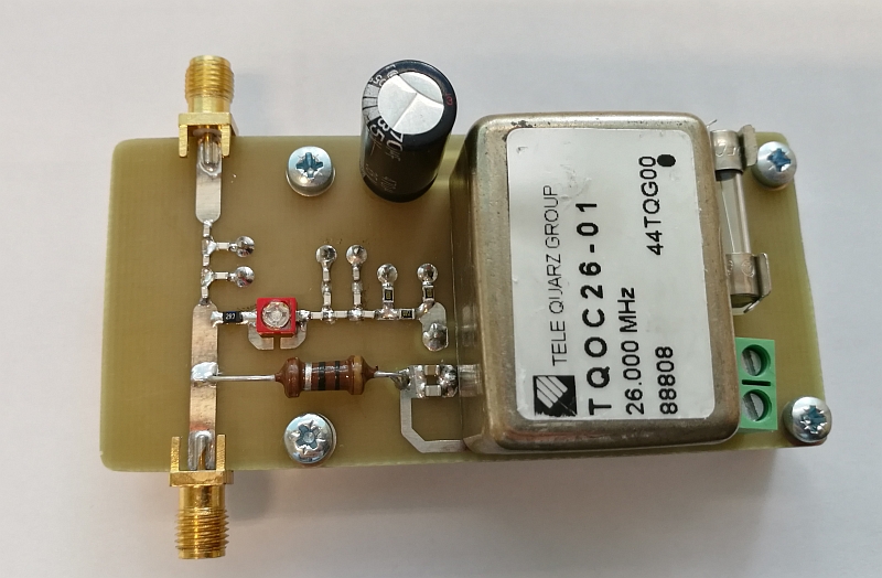
I admit, the woolly sock was close but no cigar. Still some drift in my living room, quite possibly a lot more when installed outdoors – outlook not so good. I decided to use an external 26 MHz OCXO that are ubiquitous in a land with a glorious past in GSM technology. Did you know by the way that OCXOs are like red wine, they get better with age? Anyways since I didn't fancy the idea of pulling two coaxial cables to the LNB the rather obvious choice was feeding the local through the IF coax. I made a triplexer to combine the supply DC voltage, IF and local to a single coax, it is pictured here and works well! In the local oscillator branch I included a low pass filter to reduce the square wave output of the OCXO to sine wave and an attenuator to set the level correctly. Of course, also the LNB had to be modified, its crystal had to be removed and replaced with a miniscule band pass filter. That was the tricky part, a microscope and good tweezers were a must. I got the idea from Michael, OH2AUE, his rather sophisticated modification is presented in this picture. My modification was in principle the same but not as elegant... Anyways, the key thing is that this works, and listening to the local OH3TR 10 GHz beacon verified that the LNB is now rock-stable.
Now when you are finished with this page you should check OH2AUE's AMSAT P4A Web-SDR webpage. You will see that if you are pro enough you can 3d construct 750 MHz UHF circuits with through hole components and achieve good results!!
A smart reader may have wondered how using an modified LNB as the receive converter is compatible with the dual band feed... The short answer is that its not, I plane to use two separate dishes instead, the dual band feed will be used for TX.
Updated 23.8.2018
Disclaimer: This webpage is for general information purposes only. It is not professional advice and contains opinions and most probably inaccuracies. Viewer discretion is advised.