Schematic diagram and network analyzer plot
The basic topology is simply two T-filters (lowpass and highpass) connected
together in the antenna port.
For high isolation between bands the center element of each filter
is a series resonant circuit. The center element
of the 2m branch resonates on 70cm and vice versa. This arrangement
also makes the diplexer insensitive to
terminations in 2m and 70cm ports - broadband 50 ohm environment is
never the case in practice.
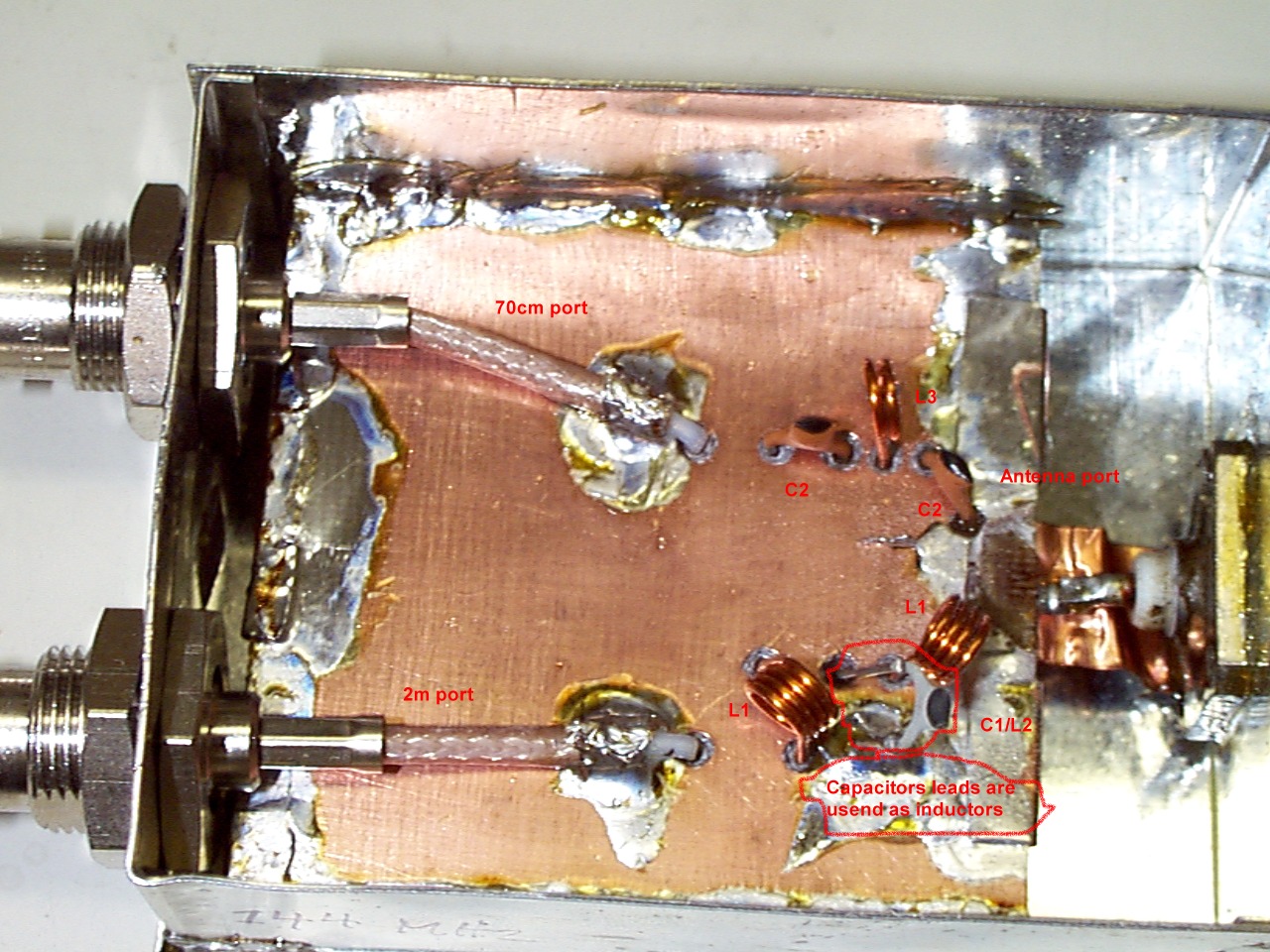
The capacitors C1 and C2 are standard ceramic capacitors. C3 is surface
mounted high-Q capacitor.
The inductors L1 and L3 are 4mm diameter aircore ones. The inductor
L2 is formed by mounting C1 approx.
1cm above the board. See picture
for my construction details. C3 is mounted on the bottom side of the PCB
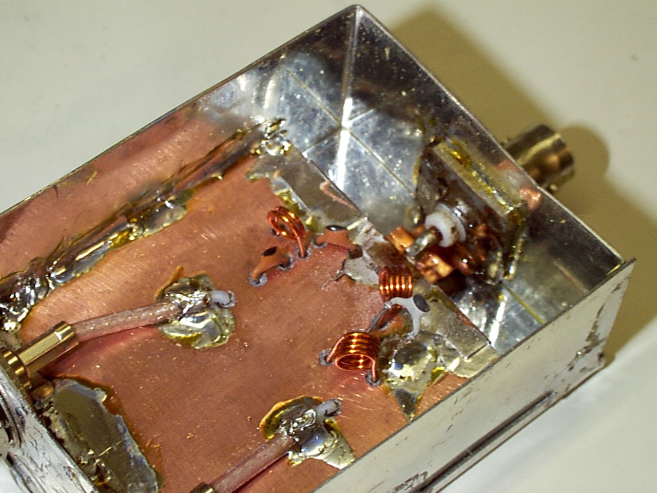
(not shown in picture). Here is another
picture from slightly different viewpoint. The diplexer is enclosed
in
a metal box and both sides of the PCB ground planes are soldered to
the walls of the box.
For best performance the series resonant circuits should be tuned for
maximum isolation. This can be easiest
done by using a network analyser (What? You don't
have a network analyser?). Alternatively the tuning can
be performed by first feeding 145 MHz RF power into the antenna
port (the 145 MHz port should be terminated
with dummy load). The power on 145 Mhz in the 434 MHz port is the minimised
by changing the mounting height
(=lead length) of C1. You should be able to measure the sub-milliwatt
level power somehow, and be sure that
you are not measuring the 3rd harmonic of 145 MHz. Then feed power
on 434 MHz into the antenna port with
434 MHz port terminated and measure the 434 MHz power in the 145 MHz
port. The 434 Mhz power can be
minimised by stretching L3 slightly. Finally, check the passband
insertion and return losses on both bands.
I have built only one piece of these diplexers and the only guarantee
I can give is that this particular one
works. No attempt has been made to reproduce the design, but the effect
of variations in component values
should be quite small because of overall low loaded-Q design. The only
critical points are the series resonant
circuits and even they are not very critical. I have not measured what
is the maximum RF power that the
diplexer can withstand, but I have used about 10W on 2m and 20W on
70cm with no problems.
Petri Kotilainen OH3MCK