Make the stub a little bit longer.
I used a minidrill and an exacto-knive.
These modifications of ancient Mobira radios are meant for licensed
radio amateur use.
In addition to this modification you also need the ham software for the
radio.
If you don't know where to find it, tough luck...
These modifications are given as an example of a modification.
Your rig may have different components, their tolerances may be somewhat
different and so on.
Please do not blame me if this doesn't work in your radio.
Make the stub a little bit longer.
I used a minidrill and an exacto-knive.
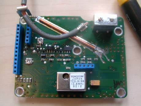
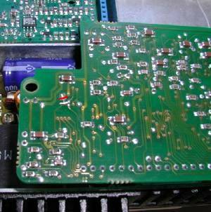
Second photograph, just that you get the picture...
There is a feedthrough hole, that you must drill open.
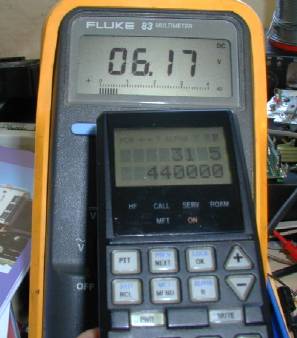
After this modification, the TX PLL lock range was 428-443 MHz.
The same method is used for RX PLL as well.
There is no need of changing any components.
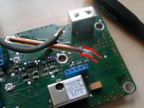
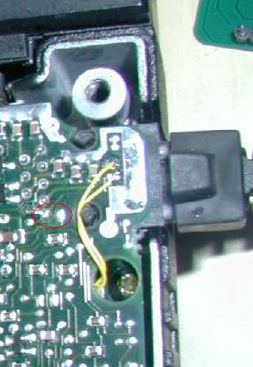
Cut away as indicated with red lines and
connect a PLL voltage test lead as indicated with yellow.
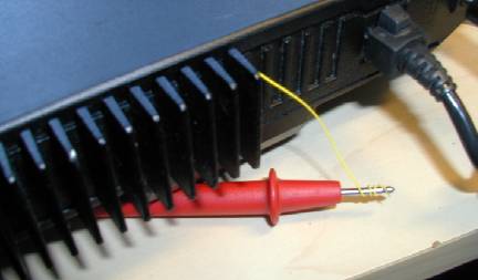
To measure the correct in operation PLL voltage,
you must close the cover.
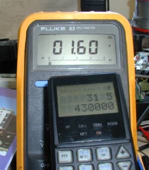
This seems ok...
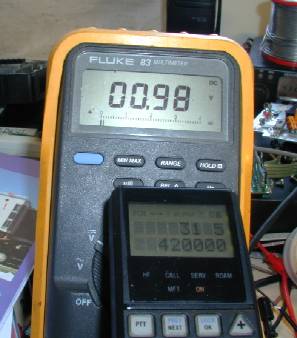
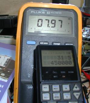
...and this is also normal.
To enable sending of CCIR tones cut the trace indicated with red
and connect it to the next trace on the board.
This modification is necessary only if you want to emit CCIR tones.
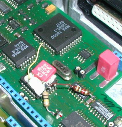
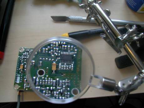
The second part of the CCIR modification involves cutting a trace
between two pins of a diode as indicated in the picture,
adding 100k and 1k resistors and a 100n capasitor. As you see
the component values are not exact, but who cares.
The yellow lead goes to the middle pin of the IC.
This modification is necessary only if you want to emit CCIR tones.
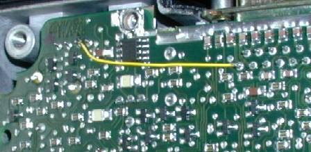
This jumper is to activate external PTT.
There is a +12V and open collector output
for a relay that will pull when TX is active.
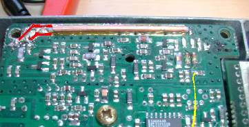
You may want to remove the 1nF capasitor as I did.
The place where the capasitor was is circled in the picture.
You must also cut the lead in the handset connector
which is connected to the collector of the
transistor as the handset pulls the line to 8V.

To change the TNC connector to BNC you must open one screw.
I used double sided tape to fix the TX/RX relay to the rig.

Remeber that the power hybride is not linear.
Install a low pass filter (better than this one) to get rid of the
harmonics.
© 2000 OH3NWQ (both the photos and the text)