Disclaimer: this is not a how-to, and must not be taken as one. Always be careful with RF power, what happens to food in a microwave must not happen to you or anyone else! See further disclaimers in the bottom of the page.
Best news: Power amplifiers can be made from surplus WCDMA base station parts.
Good news: some AMSAT P4A equipment can be used as-is!
Bad news: the feedhorns are HUGE
Worst news: the band might be full of in-band and close-by QRM, I feel I am going to need good RX filtering
What I had learned since, and what went different compared to the first version:
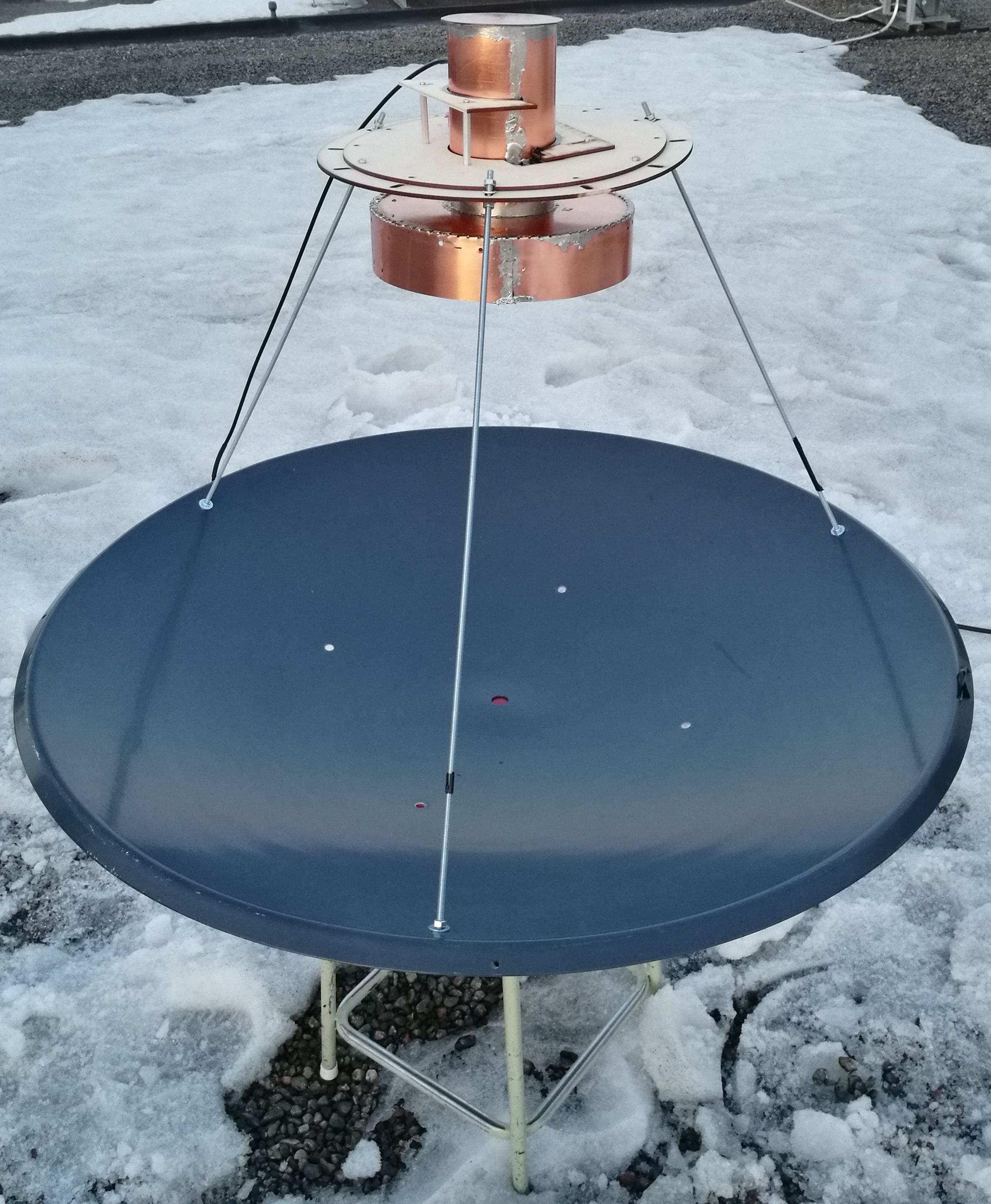
For use in the new multiband contesting system a new linearly polarized super ve4ma feed for 13 cm was built. The choke plate was made from FR4 PCB using a CNC drill at TELOK. A short MATLAB code was written to generate the required Excellon file containing the 1000 + holes! A 1 mm drill with 0.1 mm gap between holes worked well. The circular waveguide was rolled from thin sheet copper using a mandrel made from numerous laser cut circles from thick 2 mm cardboard bolted together. A lot of cardboard supports were laser cut at TUTLAB to keep the feed parts in correct place during soldering.
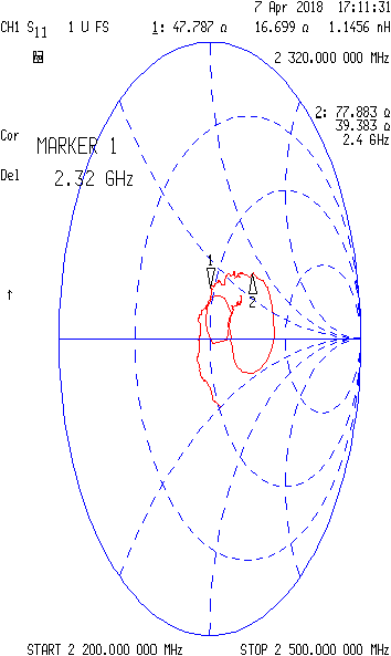
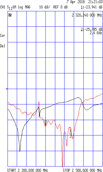
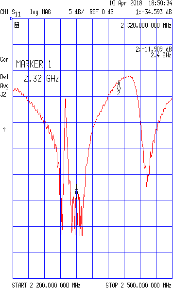
For linear polarization a probe some distance from the waveguide short (the back plate) is needed. The probe was silver-clad sheath of "86" semi rigid. A good match (return loss) was a necessity to avoid burning the resistors in the 3:1 output combiner of my high power amplifier. Contrary to many internet sources probe position 1/4 λ from the short circuit (back plate) is not good! I tried to search the internet for information on the optimal probe position/length/diameter but could not find anything useful, thus without better knowledge I drilled the hole for N connector and probe 1/4 λ (50mm) from the short, and the best match at 13 cm narrowband allocation 2.32 GHz (by trimming the probe length) was around 48+j17Ω – not good at all! I predict the optimum position is further away from the short – I should have known from my experience with similar 10 GHz feed and the W1GHz article...! I experimented with a thicker probe (6 mm copper) but the match was even worse. To improve the return loss a tuning screw was added, the best place was found by moving a screw inside the circular waveguide with a magnet while monitoring s11 on smith chart. With this single screw the return loss could be tuned to -23–24 dB , and carefully filing the probe brought this down to -29 dB. The impedance was 48-3jΩ – quite good already! The optimization was done in a long corrior without a dish antenna so further optimization (if necessary) is done outside with the dish in place to compensate the unavoidable reflections from the dish.
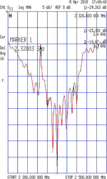
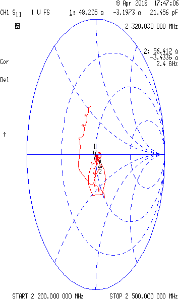
Final optimization was done outdoors with the feed fastened in front of a 100 cm dish, using a temperorary support boss cut from 4 mm plywood. Pictured here. It was quite flimsy but worked for the purpose. After some fine tuning an extremely good return loss of less than -30 dB was achieved , this being already at the limits of the calibration set.
Next goal is a proper support structure for this beauty.
This system works! It was used to have several Finland-Sweden cw qsos and several ssb/cw qsos to fellow Finnish radio amateurs in the NAC SHF contest on tuesday 22. August 2017. The key spesifications were approx. 15 W tx power and ~2.5 dB noise figure. The noise figure comes from the transverter (NF < 1dB, + relay and cabling losses inside transverter box (~0.5 dB) + feedline losses (~1 db). The noise figure of transverter box alone 1.5 dB was measured at our local club OH3TR. IN the end no external RX filtering was used, this is one of the areas where there is still room for improvement, as using an external LNA would reduce the system noise figure to less than 1 dB, but would require external band pass filtering due to high out-of-band QRM levels. So for a list of what to do next:
These improvements would combo well with permanent installation, since I don't like the idea of using a 200 W amplifier with the antenna on the same level as the user. On the other hand raising the system to a mast would require two coax runs (RX/RX) (or several relays), and in these setups and external LNA/filter would be a natural addition.
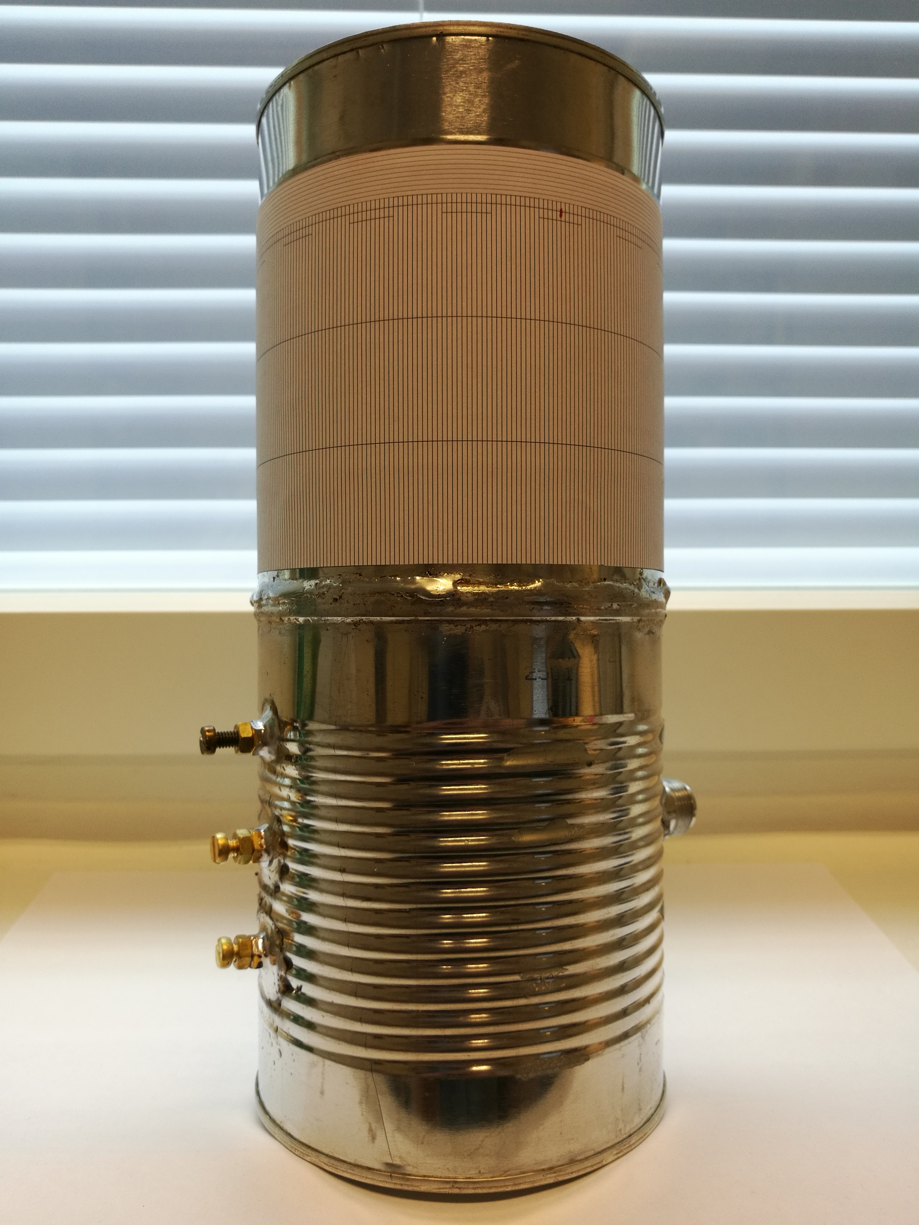
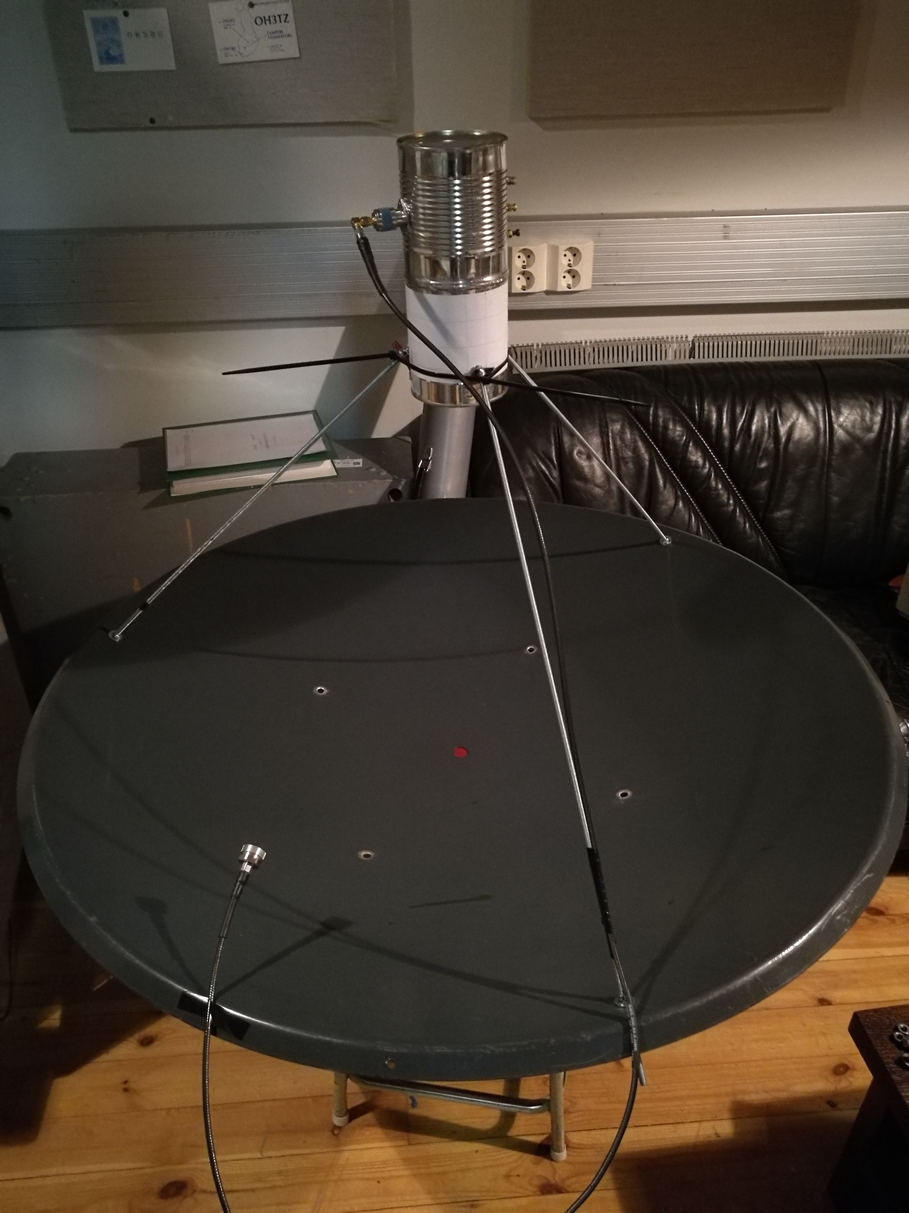
Everyhing must begin with something so heres a cantenna feedhorn. The return loss was -14...-20 dB, but depended heavily on the environment so final measurement and tuning had to be made outdoors with the feed installed. To facilitate tuning a three-screw waveguide tuner was realized, the distance of the screws was λ/8. The wavelength in a waveguide is longer compared to free space, how to calculate it is explained here! But in Finnish only. The feed was installed in place and final tuning was made outdoors with the antenna pointing towards the sky. In this way the return loss was tuned to better than 20 dB.
With a price tag of 2.40 € the feed construction really emphasized the cost reduction principles. By the way, LIDL peach cans didn't have any plastic lining, lets see how many hours/days/weeks/months(!) they last inside the clubroom. I don't think any semi-permanent installation outside is a good idea...
A power amplifier is a logical follow-up from the feedhorn. Ericsson engineers have done great work by designing a very famous UMTS SSPA module based on three MRF21120 transistors, which some argue be used pretty much as-is for amateur operation at 2.32 GHz. Very nice example can be seen on RW1AW's webpage. The original amplifier module has an aluminum heatspreader and -sink so a HUGE fan or fans are required, and the air circulation must be designed well. And even still, the performance is limited by the multiple factors, see e.g. "How to retrofit Ericsson UMTS SSPAs to obtain 300+ watts on 13cm with 2x MRF5P21180R6" by Alex, ZS6EME in DUBUS I/2017. These limitations include the excessive heat flux, the output ANAREN 3-to-1 combiner, the SMA-connector, and most probably also a number of other things. One interesting approach depicted on russian vhfdx forum seems to be to "upgrade" the output combiner by replacing the terminations with higher power ones and by replacing the output SMA connector with a N one.
For best performance you pretty much have to cut-and-paste the modules to a copper heatspreader with superior thermal properties (usually comes hand in hand with superior price tag). See how Ari, OH3LWP has done it here. Looks nice, but must have been quite a job tapping all those screw holes!
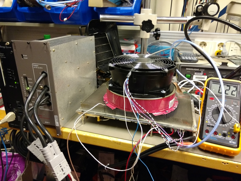
But at least for now I'm not aiming for best performance, so I'm going to try an unmodified Ericsson UMTS SSPA! After a few afternoons spent wiring the thing up and adding a big fan I got one working. In an power sweep test at Vd = 28.00 V the output P1dB power at 2320 MHz was 200 W (but remember, a measurement uncertainty always exists!). Next I did a key-down test of 3 minutes at P1dB power level to simulate WSTJ conditions. After the first minute the power output had dropped 11 %, but during the latter 2 minutes the power output dropped only 1 %. The heatsink temperature during that test remained below 40-50 ℃. While not perfect, I'd consider this acceptable at least for now. Your mileage may vary! It is worth mentioning that I did not have a temperature compensated bias. Here is a picture of the test jig. The huge RF power attenuator used in the output is not shown. The pink collar, cut from large tin can, separates the fan from the heatsink surface and improves the cooling performance of the fan. But from the sound of it the collar should have been even higher!
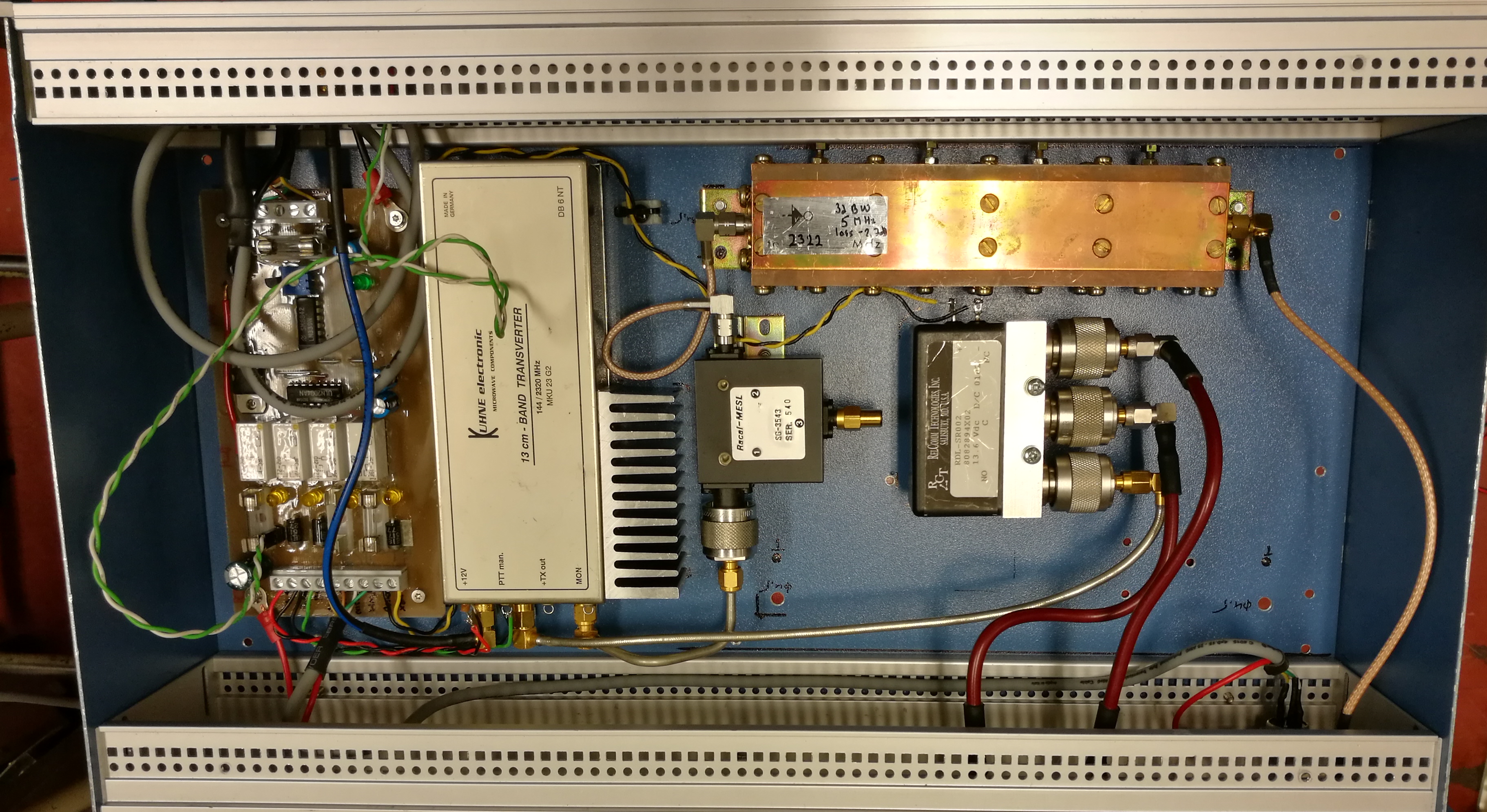
And a look inside. Converting 2320 MHz to 144 MHz IF. Pretty basic setup, DB6NT transverter, relay, sequencer, isolator and band pass filtering bolted to a nice blue aluminum box straight from the 70s(?). No external filtering in the receive chain, but you can spot the fixing point for another of those large copper band pass filters. I'll install it if the QRM level demands it. For RX/TX switching a N connectorized relay was used as I had one available, and moreover the SMA relays, like those used in my earlier 10 GHz setup were not rated for the 200 W power at 2.3 GHz.
The four-stage sequencer and power distributor board is designed by me and the PCB was manufactured at the TUT electronics club TELOK. As an improvement to my earlier designs it now incorporates overvoltage and -current protection in input/output lines. The overcurrent protection is realized using fast blow fuses and overvoltage transients are suppressed using TVS diodes. The transverter utilizes the very handy inhibit feature of my Yaesu FT-897, and is also powered from the ACC connector of the rig. In transmit it takes approximately 1 amp.As a compromise solution a medium power "TELIA" amplifier was fixed on top. This wideband amplifier is detailed in my AMSAT P4A page. The amplifier was modified by removing all three first MMIC gain stages leaving. This reduced the gain from 50 dB to 30 dB and removal of input attenuators reduced also the noise figure greatly. Moreover now I can replace the 30 dB attenuator at amplifier input with a 10 dB one which reduces the noise figure further by 20 dB.
Updated 22.11.2018
Disclaimer: This webpage is for general information purposes only. It is not professional advice and contains opinions and most probably inaccuracies. Viewer discretion is advised.