10 GHz säätäjä Tampereelta
Alempien bandien antennit ovat liian isoja! - Antennas for lower bands are too big!
To have even moderate success in the regional Nordic Activity Contest (NAC) SHF it is essential to operate on as many bands from 13 cm up as possible! I saw an error in my ways: the two systems I had built were so different that it took about an hour to change from 13 cm to 3 cm and vice versa. How terrible! I had to replace pretty much everything from the feedpoint to the cabling. So to amend the situation I decided to rebuild my 10 GHz setup in way compatible with the 13 cm unit.
So far I have:
The next big thing may not be MaaS but rather:
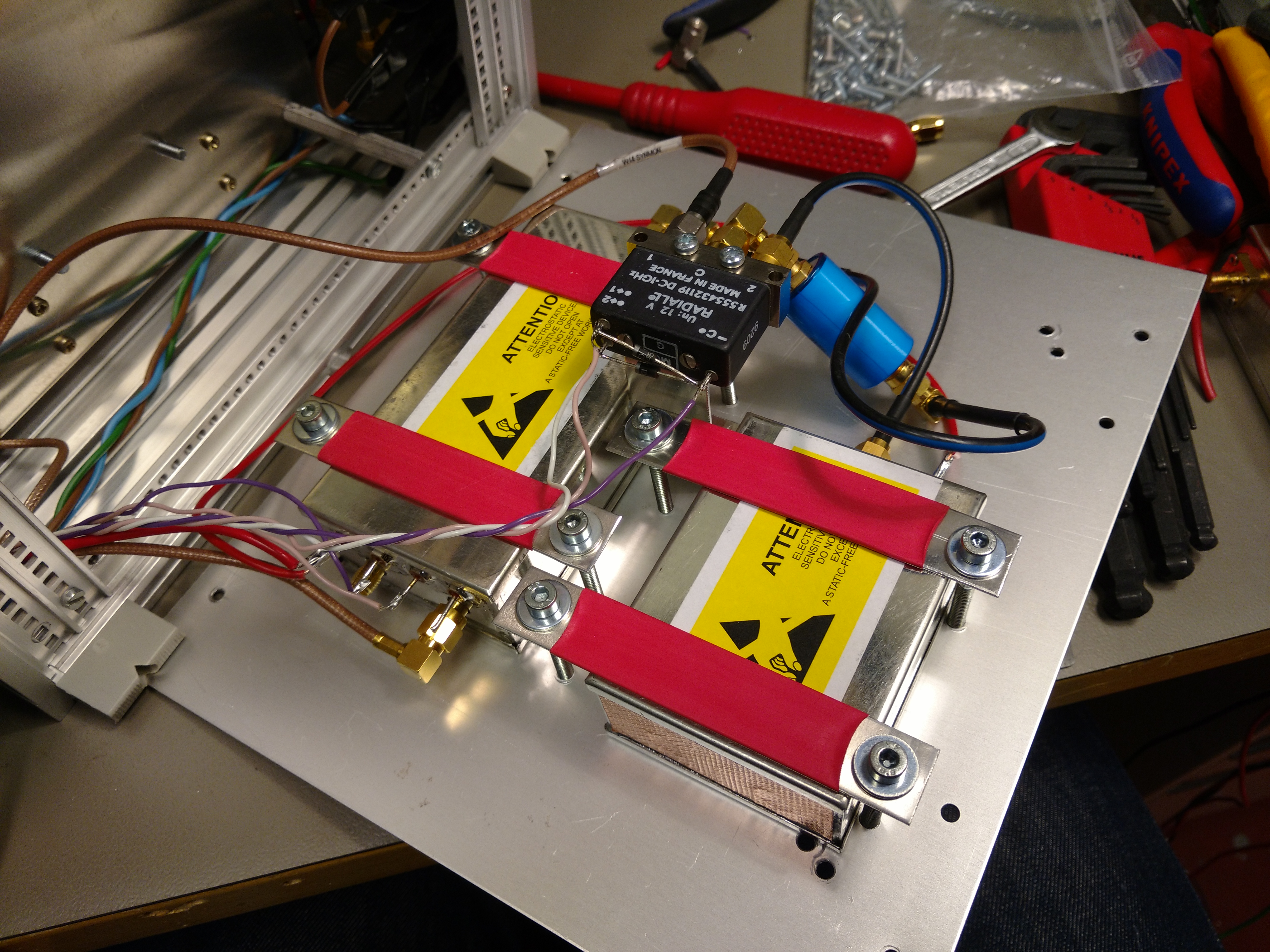
The transverters share the same IF, RF and control connectors (I used threaded DIN connectors for this) so same cabling can be used to connect to the FT-897. In the future I can also build a box with a lot of DIN connectors and one 4-to-1 SMA relay (already have one actually) to switch between up to four transverters! In this revision I decided to sacrifice some receive sensitivity for simplicity by placing the LNA and relay in the transverter enclosure instead of at the feedpoint as was done previously. This however allows me to use just one cable to connector the transverter to the feedhorn! Simple, and modern Sucoflex cables have less than 1 dB loss on 10 GHz...
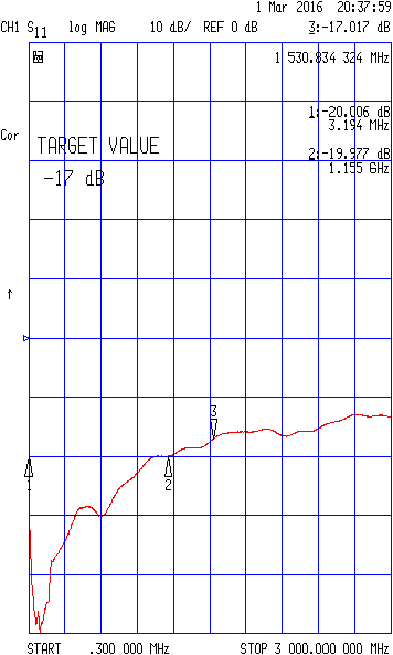
Why not make a feed for ALL the microwave bands, from 1.3G to 10G? Good question! See my solution here. Some of the dimensions for 23 and 13 cm are from Rastilav's (OM6AA) and Hazdra's article "Loop Feed With Enhanced Performance"; I scaled the dimensions for higher bands were scaled from the data presented. From my attempts at tuning this thing I reckon the band-to-band coupling can be quite high – protect your LNAs when operating other bands at high power...! Tuning this feed was tricky, so far I have excellent < -20 dB return loss at 23, 13 and 3 cm, but rather poor ≈ -10 dB return loss at 9 and 6cm. Another evening in the RF lab or an isolator will required, but first I'll direct my resources to getting some equipment for these bands!
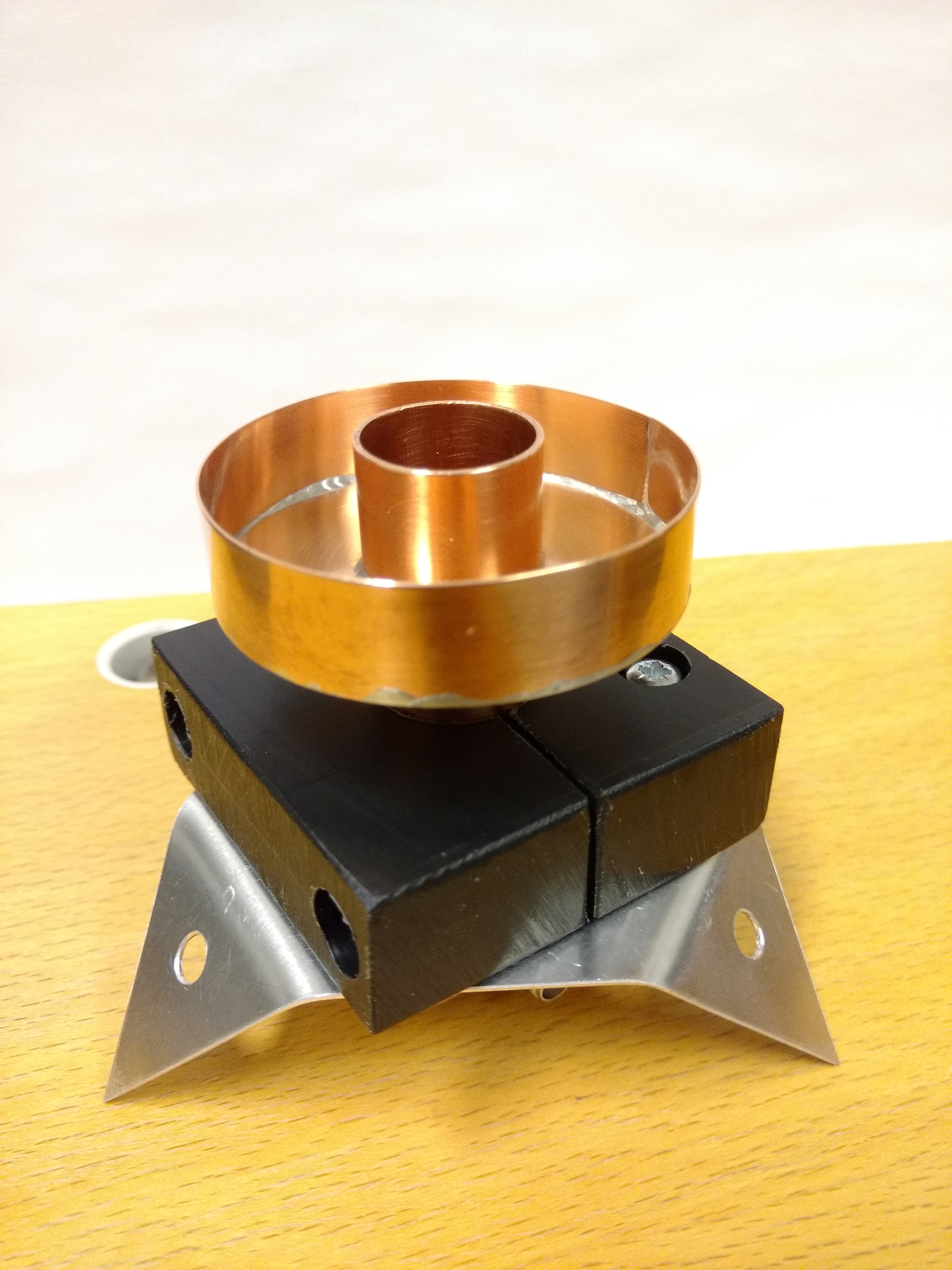
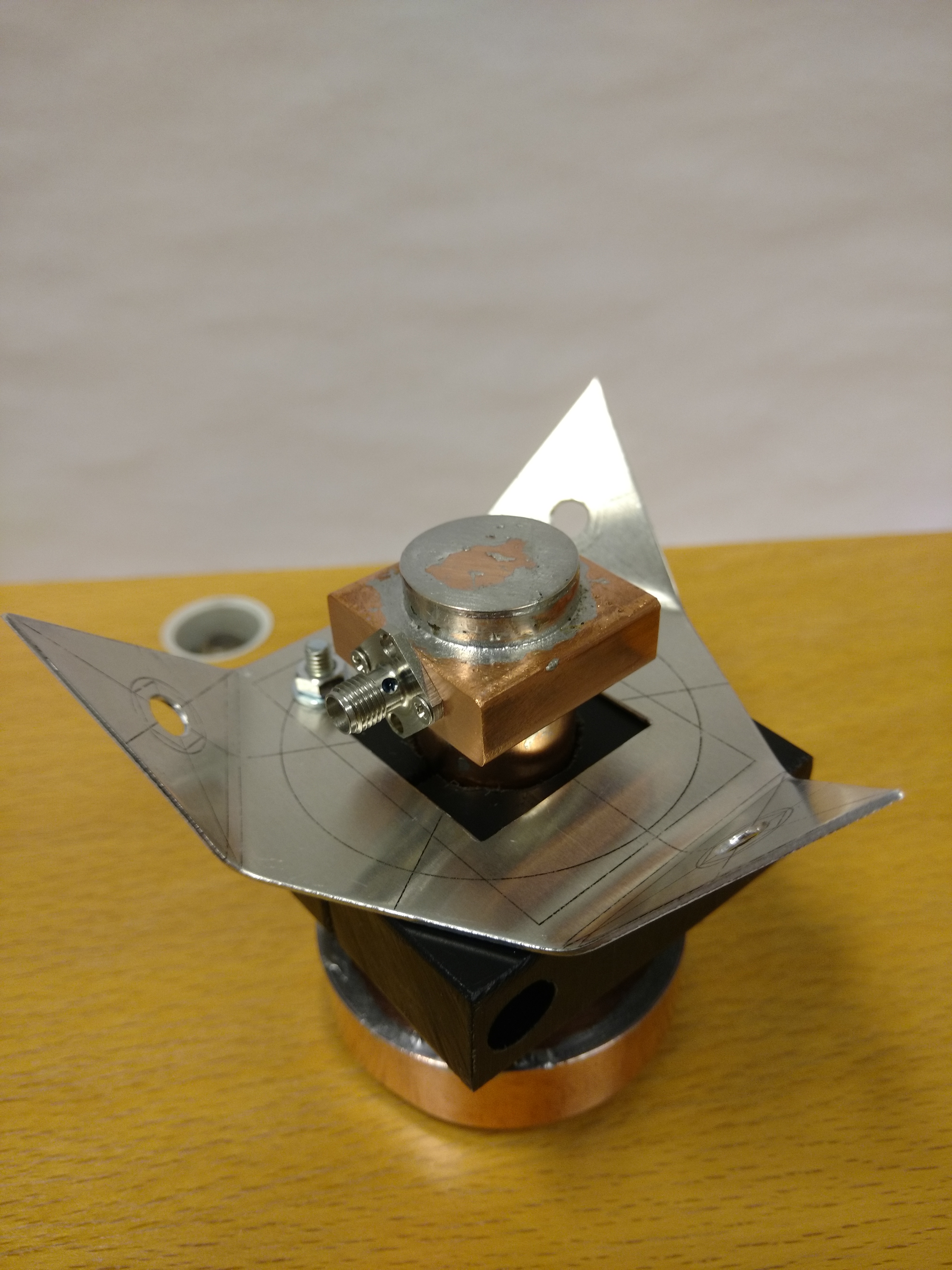
I have learned from experience that a robust feedhorn support is mandary. See my attempt here. The green stuff is polyethylene, really easy and nice plastic to mill.
With AMSAT P4A almost here (scheduled for launch in 2018) its time to build equipment for it. See my AMSAT P4A page.
Largest dish that may fit in a van, also large enough for EME work. VK7MO and VK3XPD have done it even with a small ~64 cm dish! Just needs lots of TX power to hear own echoes, good thing up to 600 W is allowed and the price of GaN semis seems to be dropping and their power output seems to be going up.
I almost had this, a reinforced surveyor's tripod and a heavy duty CCTV camera rotator. But it all failed because the old PVC insulation of the rotator AC motors had degraded to something rock-hard and brittle - it could be snapped by gently bending! Those motors have not been in production for ages, and thus buying new replacements was not possible. Hundreds hours of work ruined because of PVC plastic.
My advice? Stay away from PVC! It will not stand the test of time. Moreover it not even a good electrical insulator! It is said that "The PVC molecule is strongly polar in character and , consequently, leads to intense dielectric losses. For this reason, its use as a dielectric has been greatly restricted to lower frequencies and lower voltages." [direct quote from R. Bartnikas and R. Eichhorn: Engineering Dielectrics Volume IIA : Electrical Properties of Solid Insulating Materials, ASTM International, 1983].
Designing LNAs with MMICs is fun, and at low bands (like 2m) 1:1 match can be achieved with QucsStudio simulation! Link to my PGA-103+ LNA page.
FT8 was too fun to miss so I had to give it try in my city full of RF noise. Great success was had with a small magned loop antenna! Link to my hf page.
The FT8 mode on HF was exactly as fun as people had let me to believe! The interface is nothing fancy, opa2132 -based audio buffers, isolation transformers, only polyester capacitors in signal path and single-supply operationg following this excellent article from Analog Devices.
I wanted to try out the FT-8 mode everybody talks about and participate in the "fish cock" contest on 2.4.2018. Unfortunately the QRM where I live is so heavy I have to drive a few hours and set up a fiberglass mast to operate HF. Setting it up takes less than 2 hours so it would be perfect for field trips if I could motivate other HAMs to participate in one! Antenna of choice is a G5RV optimized for my fiberglass mast installation, it works better than any of the at least 4 OCFDs I have tried earlier. The inverted-V installation is excellent for the Finnish fish cock contest.
Replacing one PIN diode brought the UHF TX of good old FT-897 back to life, more here.
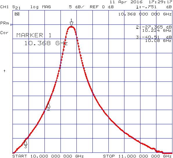
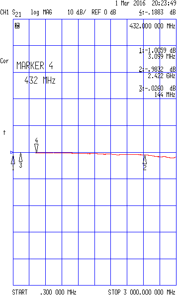
I like my new-ish (only 10 years old) FT-897, it has a good VFO. I did not dare to modify it like I did with my old FT-817, so I opted to take transverter RTX control from the ACC jack. It has PTT and a +13.8 V supply so one PNP transistor is necessary to provide the +V on transmit. Horrible "3D construction" is revealed here. Built using ATC 100 series capacitor for higher power handling. S21 Measurement shows it may be good at least for 2m and 70 cm. To prevent possible damage from ALC power spikes when turning on TX I run it through a 10dB/50W attenuator. ALC power spiking seems to be a well-recognized problem, more information can be found from e.g. oh4fr and lz4tu webpages. I repeated the measurements using vector signal analyzer in zero span mode and rather unsurprisingly got similar results.
An aluminum block was machined to fix the rotator to the tripod. The rotator speed can be varied, and the accuracy is good for the beamwidth of few degrees. The first test with this setup did not go well - RX was very deaf and only very weak signal got through to other stations. The problem? - loose SMA connectors! The situation was corrected by using a high quality HUBER+SUHNER SMA moment wrench. All connections in the system were checked and several loose ones were corrected. This ought to improve the performance many dBs, and it did, in the next test QSOs were had with several Swedish (and of course also Finnish) stations! My advice? Beware of loose SMA connectors, investing in a good moment wrench may more than double your QSOs on the higher bands ☺
First QSOs in NAC SHF test on 25th October 2016. Total of four QSOs and new distance record 317 km to SK0EN at JO99jx. Significantly improved (15 dB) gain compared to the horn setup; yet beaming was easier than I had thought. L. Manfrotto has indeed made excellent tripods, yet this felt like the limit. Next project goal will be a sturdier mount and remote rotation (its cold outside...) Notice the all-incluside weather protection.
The new LNA and the ve4ma feed bolted together and connected with 141 handyform coax. Bending the handyform cables was fun! The hardest part was finding suitable short pieces of low-loss coax. Lots of semirigid and handyform pieces were measured for losses, and many promising candidates were found to exhibit higher losses or to be outright broken. The best piece of coax was actually shipped to be from the other side of Finland, thanks! Would that have something to do with the fact they were thrown in the dumpster...?
My advice is to cut faulty pieces of coax cables to max 10 cm or 1/10 of total weight pieces before throwing them away!
More gain to hear better. Considering the combined losses of rx BPF, isolator and cabling at least around 15...20 dB is needed to prevent them from degradating the rx noise figure. Luckily M. Kuhne has the answer. In the beginning there was a question of whether the LNA should be powered on during TX. Some argued this would help the LNA survive the signal leaked through the finite isolation of the SMA relay, on the other hand if this signal was amplified it could harm the subsequent transverter RX stages. Calculations using the manufacturer reported minimum isolation (of the relay) the RF power at the transverter RX input could have been around ~0 dBm (too high). On the other hand some argued that the actual isolation of SMA relays can be several tens of dB's higher than what is reported. Measurements would have been needed.
But its always good thing to ask! I asked Kuhne Electronics for their recommendation which was to turn the LNA off during transmit. I had to modify the transverter box and sequencer logic to do this but in the end it was most probably were the simplest and therefore the best approach.
G4HUP made an excellent kit for this. Some argue this can help making QSOs with non-gps-locked local. The hardest part was drilling the SMA connector hole to ft-817. This had the possibility of going horribly wrong. I removed the PCB assy from the "drilling side" and the front panel and made an effort to cover everything else with masking tape and paper. The reason for this is laziness and removing the power amp and filter assy would have required reapplying thermal pastes.
During hand drilling and derurring/filing I held a vacuum cleaner nozzle under/on the side of the working area to suck out any metal particles. I cannot recommend this for anyone, its rather nerve-wracking. As a result the the radio and IF tap works for now. In my version the IF tap is from before the first filter, as a result I see strong spurious (LO?) some hundred kHz down. Can't comment on if this is a normal thing or not.
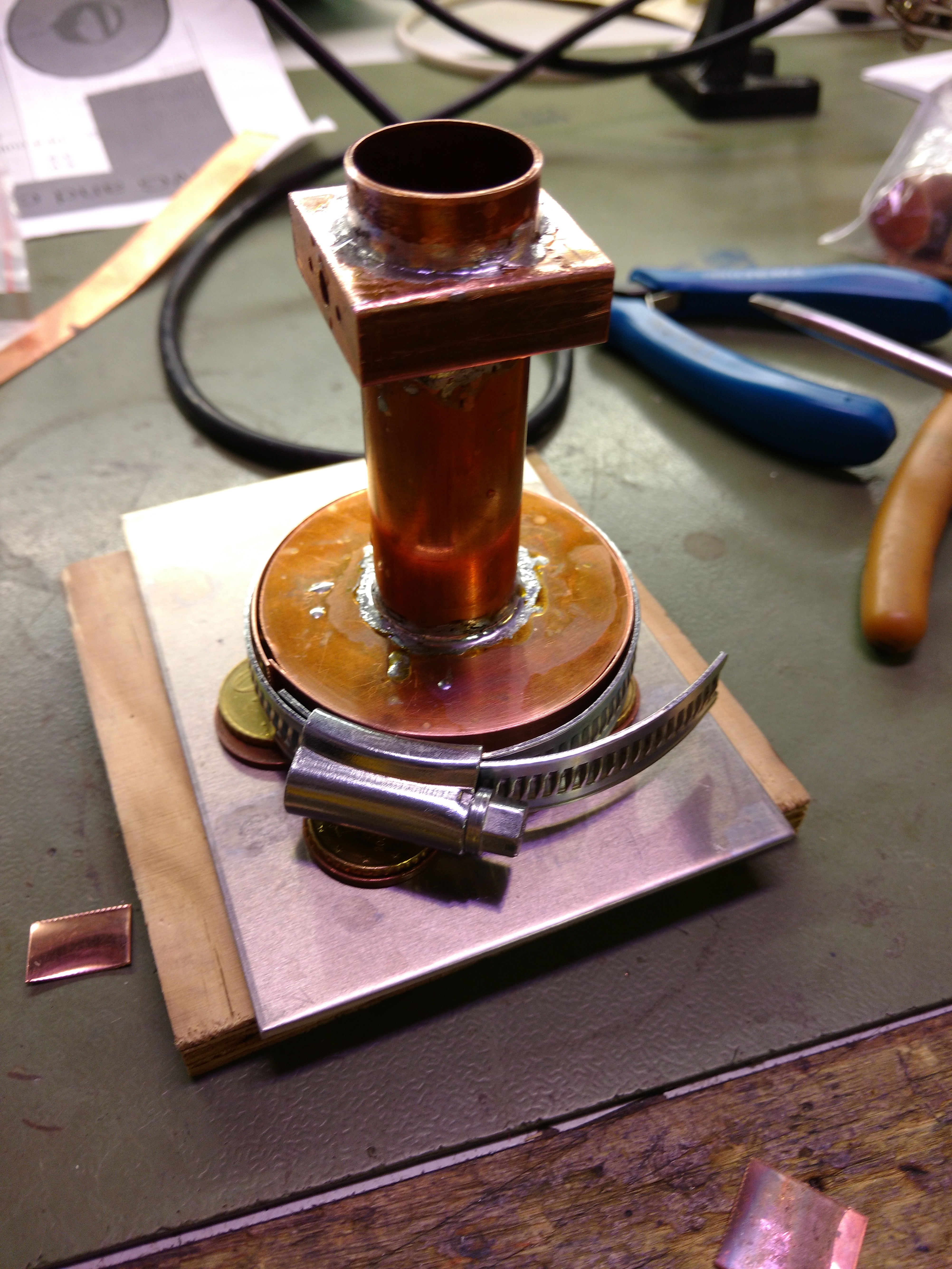
Feed itself and how the choke ring was soldered
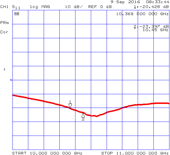
Return loss was ok (-20 dB), could have been made better but I was lazy.
Smith chart shows correct steps for future improvement: less backshort and shorter probe length
Feedhorn support boss, another image,from 6000-series easy-to-bend 1 mm aluminum and 20 mm polyoxymethylene plastic. Its easy to machine with hand tools. Its for portable work on nice weather only so no weatherproofing and zinc plated screws
Return loss was ok, around -18 dB. Could have been made better if I had had the skills to drill in the middle of wr-75 waveguide to do a better sma transition. Too bad I only had one chance :D. This was used for QSOs with Ari, oh3lwp some kilometer away.
TX power was 2.5 watts minus cable and relay losses (~4 dB?), LNA had noise figure of 1.2 dB and gain of 9.5 dB. The rx was gain-limited because of cable, isolator and bandpass filter losses, yet I managed to hear two(!) SSB stations from southern Finland, but neither heard me. Clearly the way of oikea ja uskottava radioamatööri is to increase TX power.
Its a 106.5 MHz OCXO I spend bazillion hours with. It worked ok but was extremely sensitive to vibrations, since even slight changes in physical dimensions would change frequency. Not much, but after multiplied by 96 (for 10224 MHz LO) the vibrations were clearly audible. The worst part? The equipment I salvaged the ocxo portion from came with a nice metal cover which I could have cut off and screwed on top of it = no changes stray capacitance, yet I had thrown it away. I made a DIY cover from sheet copper but it was not enough to stabilize the thing. Now I use a cheap 10 MHz OCXO module and a pll to drive the multiplier chain. 10 MHz is your friend because with it I can upgrade to gps (or rubidium) locked oscillator when the time for EME comes.
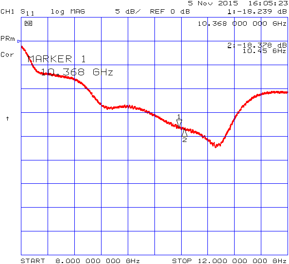
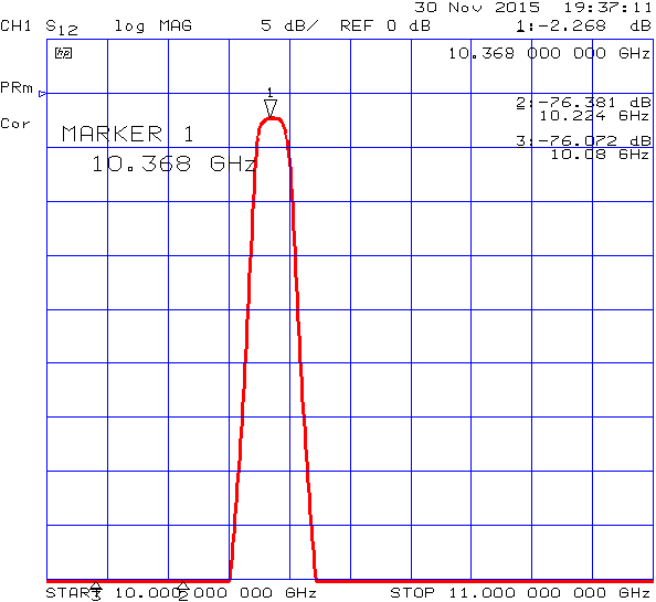
W1GHZ design, thanks for the work you have done! Clearly I did not read the paper properly and the distance between first filter element and the sma transition probe is less than the recommended one waveleght. Nevertheless it works well, with only 0.75 dB losses. I use it in TX chain to filter out LO emissions.
Compared to my first attempt with WR-75 this went way better, mainly due to the documentation by W1GHZ. This time the return loss was below -34 dB.
Losses were acceptable and return loss was ok. Used to inject 5 V on TX from modded ft-817 to 144 MHz IF coax. I really like a system with just two cables between transverter and IF rig: 13.5 V DC line and rg223 if coax.
Have you tried this – no promise this works as intended though!
Measurement Mode "Special Function 1.4" is for frequency converting DUTs with a variable IF output ranging from 10 to 1600 MHz and a fixed LO, which may be controlled (if desired) by the Noise Figure Meter.“ (from HP 8970B operating manual, page 3-151). Sounds a lot like a transverter doesnt it? So here we go, the page numbers refer to the HP 8970B manual.
Note that the transverter bandwidth must be broad enough (4 MHz or broader, page 1-9) or the NFM will give erroneous results
For a 1.28 mm probe diameter (typical for SMA connector) the correct backshort (distance between probe center and back wall) for 20.0 ID copper tubing is 10.9 mm. You can calculate this from Figure 17 presented in the paper Understanding Circular Waveguide—Experimentally by scaling using ratio of the pipe inside diameters. As long as you remember that the reference 3/4" tubing has nothing to do with 3/4", having an inside diameter of 0.81" instead. This took me 2 attempts and 2 years to find out.
Example: We have 20.0 mm ID tube and 1.28 mm (approx 0.05 inches ) probe. Scaling from Fig. 17 yields probe diameter of 1.28 mm *(20.574 mm/20.0 mm) = 1.32 mm (=0.052 inches). That gives us backshort of approx 0.44" = 11.176 mm and probe length of 0.25" = 6.35 mm. By scaling back to our 20.0 ID tube we get backshort of (20.0 mm /20.574 mm)*11.176 mm = 10.86 mm and probe length of 6.17mm.
Updated 31.10.2018
Disclaimer: This webpage is for general information purposes only. It is not professional advice and contains opinions and most probably inaccuracies. Viewer discretion is advised.